警告
本节包含从C++自动翻译到Python的代码片段,可能包含错误。
坐标系
关于绘图系统使用的坐标系的信息。
坐标系由QPainter类控制。与QPaintDevice和QPaintEngine类一起,QPainter构成了Qt绘图系统Arthur的基础。QPainter用于执行绘图操作,QPaintDevice是一个可以使用QPainter进行绘制的二维空间的抽象,而QPaintEngine提供了画家用于在不同类型设备上绘制的接口。
QPaintDevice 类是能够被绘制的对象的基类:它的绘图能力被 QWidget、QImage、QPixmap、QPicture 和 QOpenGLPaintDevice 类继承。绘图设备的默认坐标系的原点位于左上角。x 值向右增加,y 值向下增加。默认单位在基于像素的设备上是一个像素,在打印机上是一个点(1/72 英寸)。
逻辑QPainter坐标到物理QPaintDevice坐标的映射由QPainter的变换矩阵、视口和“窗口”处理。默认情况下,逻辑和物理坐标系是重合的。QPainter还支持坐标变换(例如旋转和缩放)。
渲染
逻辑表示
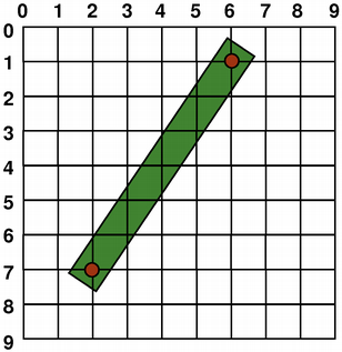
图形原语的大小(宽度和高度)始终与其数学模型相对应,忽略渲染时使用的笔的宽度:
QRect(QPoint(1, 2), QPoint(7, 6))
QLine(QPoint(2, 7), QPoint(6, 1))
QLine(2, 7, 6, 1)
QRect(QPoint(1, 2), QSize(6, 4))
QRect(1, 2, 6, 4)
别名绘画
在绘制时,像素渲染由Antialiasing渲染提示控制。
RenderHint 枚举用于指定可能被任何给定引擎遵守或不遵守的标志给 QPainter。Antialiasing 值表示引擎应尽可能对图元的边缘进行抗锯齿处理,即通过使用不同的颜色强度来平滑边缘。
但默认情况下,画家是抗锯齿的,并且适用其他规则:当使用一像素宽的笔渲染时,像素将被渲染到数学定义点的右侧和下方。例如:
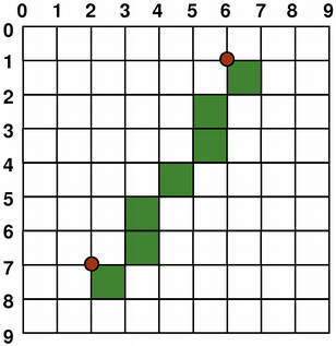
当使用偶数像素的笔进行渲染时,像素将在数学定义的点周围对称渲染,而使用奇数像素的笔进行渲染时,多余的像素将像单像素情况一样渲染到数学点的右侧和下方。具体示例请参见下面的QRectF图表。
QRectF
逻辑表示
一像素宽的笔
两像素宽的笔
三像素宽的笔
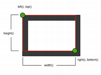

请注意,由于历史原因,QRect::right() 和 QRect::bottom() 函数的返回值与矩形的真实右下角有所偏差。
QRect的right()函数返回left() + width() - 1,bottom()函数返回top() + height() - 1。图中的右下角绿点显示了这些函数的返回坐标。
我们建议您直接使用QRectF:QRectF类使用浮点坐标在平面上定义一个矩形以确保精度(QRect使用整数坐标),并且QRectF::right()和QRectF::bottom()函数确实返回真正的右下角。
或者,使用QRect,应用x() + width()和y() + height()来找到右下角,并避免使用right()和bottom()函数。
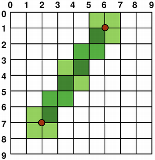
抗锯齿绘画
如果你设置了QPainter的anti-aliasing渲染提示,像素将在数学定义点的两侧对称渲染:
转换
默认情况下,QPainter在关联设备的自身坐标系上操作,但它也完全支持仿射坐标变换。
你可以使用scale()函数按给定的偏移量缩放坐标系,使用rotate()函数顺时针旋转它,并使用translate()函数平移它(即向点添加给定的偏移量)。
你也可以使用shear()函数围绕原点扭曲坐标系。所有的变换操作都在QPainter的变换矩阵上操作,你可以使用worldTransform()函数来检索这个矩阵。矩阵将平面上的一个点转换为另一个点。
如果你需要反复进行相同的变换,你也可以使用QTransform对象以及worldTransform()和setWorldTransform()函数。你可以随时通过调用save()函数保存QPainter的变换矩阵,该函数将矩阵保存在内部堆栈中。restore()函数将其弹出。
变换矩阵的一个常见需求是在各种绘图设备上重复使用相同的绘图代码时。如果没有变换,结果将紧密依赖于绘图设备的分辨率。打印机具有高分辨率,例如每英寸600点,而屏幕通常每英寸有72到100点。
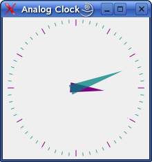
模拟时钟示例
模拟时钟示例展示了如何使用
QPainter的变换矩阵来绘制自定义小部件的内容。我们建议在进一步阅读之前编译并运行此示例。特别是,尝试将窗口调整为不同的大小。
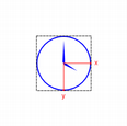
We translate the coordinate system so that point (0, 0) is in the widget’s center, instead of being at the top-left corner. We also scale the system by
side/ 200, wheresideis either the widget’s width or the height, whichever is shortest. We want the clock to be square, even if the device isn’t.This will give us a 200 x 200 square area, with the origin (0, 0) in the center, that we can draw on. What we draw will show up in the largest possible square that will fit in the widget.
See also the Window-Viewport Conversion section.
painter.save()
painter.rotate(30.0 * ((time.hour() + time.minute() / 60.0)))
painter.drawConvexPolygon(hourHand, 4)
painter.restore()
We draw the clock’s hour hand by rotating the coordinate system and calling
drawConvexPolygon(). Thank’s to the rotation, it’s drawn pointed in the right direction.The polygon is specified as an array of alternating x, y values, stored in the
hourHandstatic variable (defined at the beginning of the function), which corresponds to the three points (7, 8), (-7, 8), (0, -40).The calls to
save()andrestore()surrounding the code guarantees that the code that follows won’t be disturbed by the transformations we’ve used.painter.setBrush(minuteColor) painter.save() painter.rotate(6.0 * time.minute()) painter.drawConvexPolygon(minuteHand, 4) painter.restore()After that, we draw the hour markers for the clock face, which consists of twelve short lines at 30-degree intervals. When that loop is done, the painter has been rotated a full circle back to its original state, so we don’t need to save and restore the state.
painter.save()
painter.rotate(6.0 * time.second())
painter.drawConvexPolygon(secondsHand, 4)
painter.drawEllipse(-3, -3, 6, 6)
painter.drawEllipse(-5, -68, 10, 10)
painter.restore()
We do the same for the clock’s minute hand, which is defined by the three points (7, 8), (-7, 8), (0, -70). These coordinates specify a hand that is thinner and longer than the minute hand.
for j in range(0, 60):
    painter.drawLine(92, 0, 96, 0)
    painter.rotate(6.0)
Finally, we draw the minute markers for the clock face, which consists of sixty short lines at 6-degree intervals. We skip every fifth minute marker because we don’t want to draw over the hour markers. At the end of that, the painter is rotated in a way which isn’t very useful, but we’re done with painting so that doesn’t matter.
有关变换矩阵的更多信息,请参阅QTransform文档。
窗口-视口转换
当使用QPainter进行绘制时,我们使用逻辑坐标指定点,然后这些点会被转换为绘图设备的物理坐标。
逻辑坐标到物理坐标的映射由QPainter的世界变换worldTransform()(在变换部分中描述)以及QPainter的viewport()和window()处理。视口表示指定任意矩形的物理坐标。“窗口”描述逻辑坐标中的相同矩形。默认情况下,逻辑和物理坐标系重合,并且等同于绘制设备的矩形。
使用窗口-视口转换,您可以使逻辑坐标系适应您的偏好。该机制还可以用于使绘图代码独立于绘图设备。例如,您可以通过调用setWindow()函数,使逻辑坐标从(-50, -50)扩展到(50, 50),并将(0, 0)置于中心:
painter = QPainter(self)
painter.setWindow(QRect(-50, -50, 100, 100))
现在,逻辑坐标 (-50,-50) 对应于绘图设备的物理坐标 (0, 0)。无论绘图设备如何,您的绘图代码将始终在指定的逻辑坐标上操作。
通过设置“窗口”或视口矩形,您可以对坐标进行线性变换。请注意,“窗口”的每个角都映射到视口的相应角,反之亦然。因此,通常建议让视口和“窗口”保持相同的宽高比,以防止变形:
side = qMin(width(), height())
x = (width() - side / 2)
y = (height() - side / 2)
painter.setViewport(x, y, side, side)
如果我们将逻辑坐标系设置为正方形,我们也应该使用setViewport()函数将视口设置为正方形。在上面的示例中,我们使其等同于适合绘图设备矩形的最大正方形。通过在设置窗口或视口时考虑绘图设备的大小,可以使绘图代码独立于绘图设备。
请注意,窗口-视口转换仅是一种线性变换,即它不执行裁剪。这意味着如果你在当前设置的“窗口”之外进行绘制,你的绘制仍然会使用相同的线性代数方法转换到视口。
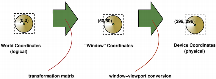
视口、“窗口”和变换矩阵决定了逻辑QPainter坐标如何映射到绘制设备的物理坐标。默认情况下,世界变换矩阵是单位矩阵,“窗口”和视口设置等同于绘制设备的设置,即世界、“窗口”和设备坐标系是等价的,但正如我们所看到的,可以使用变换操作和窗口-视口转换来操纵这些系统。上图描述了这一过程。
另请参阅
模拟 时钟